
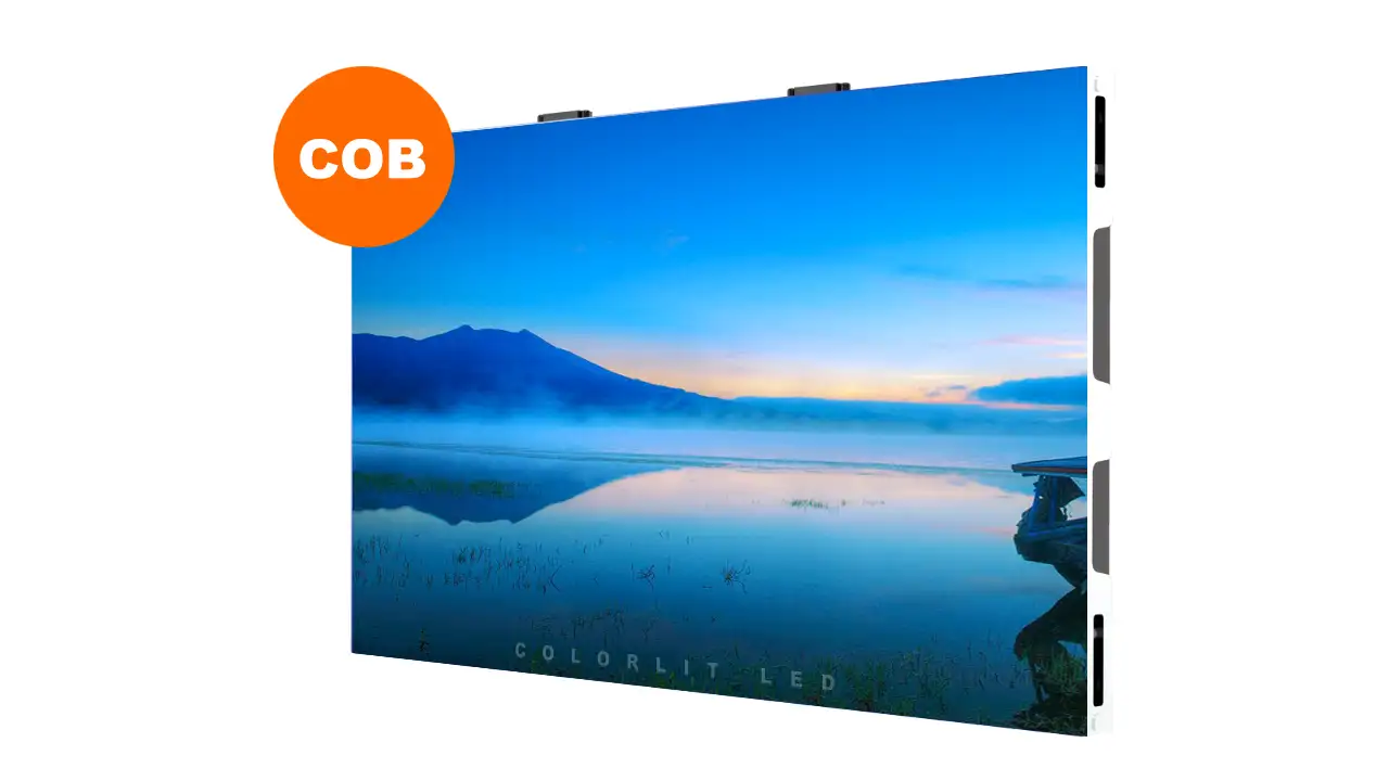
Understanding and utilizing flip chip COB LED display technology is an important aspect of sourcing high-performance, next-generation visual solutions. As a result, you can achieve superior image quality and long-term reliability, ensuring your investment delivers exceptional value and performance.
In this blog post, I’ll explain the concept of flip chip COB, its importance in the display industry, the different types of encapsulation, and how to effectively evaluate its pros, cons, and applications to boost your display strategy.
Table of Contents
1. What is Flip Chip COB Encapsulation?
Flip Chip COB (Chip On Board) encapsulation is a cutting-edge LED packaging technology where the LED chips are mounted directly onto the PCB (Printed Circuit Board) with their electrodes facing down, in contrast to the traditional “face-up” method. In this structure, the chips are “flipped,” allowing direct electrical and thermal contact between the chip and the board. The entire assembly is then encapsulated with a protective resin.

This direct mounting method brings fundamental changes to how LEDs are manufactured and used. By removing wire bonding—a critical and delicate step in traditional LED packaging—flip chip COB enables a simpler, more integrated, and reliable design. The process typically involves die attach, flip-chip bonding, encapsulation, and curing, resulting in a highly compact and robust structure
As demand for higher resolution, greater reliability, and diverse application scenarios increases, the limitations of traditional Surface Mount Device (SMD) LEDs and face-up COB have become more pronounced. Flip chip COB displays address these gaps by leveraging an innovative packaging technology. It can enhance both the performance and durability of LED display.
2. How Flip Chip COB Packaging Differs from Traditional COB
To fully appreciate flip chip COB Packaging, it’s essential to understand how it differs from both traditional COB (face-up).

The most significant distinction for flip chip COB is the elimination of wire bonding. In face-up COB, thin gold (or copper) wires connect the chip’s electrodes to pads on the PCB. This step introduces reliability risks (wire breakage, poor contact, or corrosion), limits how close chips can be placed, and can reduce light output by blocking some of the emission area.
Flip chip COB’s direct connection removes these issues, allowing for higher packing density, better thermal management, and greater mechanical robustness.
Here are some differences between face-up COB LED and flip chip COB LED for your reference:
| Feature | Face-Up COB | Flip Chip COB |
| Chip Orientation | Electrode facing up | Electrode facing down |
| Connection Method | Requires wire bonding | Direct bonding to PCB |
| Thermal Management | Longer thermal path; less efficient | Shorter thermal path; more efficient |
| Reliability | Prone to wire bond failures | Higher reliability; fewer failure points |
| Pixel Pitch | Limited by wire bonding | Supports smaller pixel pitches (sub-1mm) |
| Assembly Complexity | More complex due to wire bonding | Simpler assembly process |
| Light Emission | Reduced by wires and electrodes | Maximized light emission area |
| Repairability | Individual LED repair possible | Typically not repairable at pixel level |
| Cost | Generally lower initial cost | Higher initial cost but lower total cost of ownership |
| Applications | Suitable for larger pixel pitches | Ideal for high-resolution and micro-LED displays |
3. Why Flip Chip COB? Technology Origins and Evolution
The origins of flip chip technology date back to the semiconductor industry, where “flip chip” bonding was developed to improve the performance and density of integrated circuits. In the LED field, this approach was adapted to address the growing need for high-resolution, reliable, and thermally efficient displays.

Initially, most LEDs used the face-up structure, as it was simpler and more mature. However, as market demand shifted toward finer pixel pitches and higher performance, the limitations of face-up chips—especially the need for wire bonding and the inefficiency in heat dissipation—became more apparent.
This drove the industry to explore alternative packaging methods, leading to the development and adoption of flip chip technology within the COB framework.
Flip chip COB encapsulation allows for higher current densities, more uniform current distribution, and improved efficiency. The direct connection between the chip and the substrate shortens the thermal path, allowing heat to be conducted away more quickly. This not only improves the performance and lifespan of the LEDs but also makes it possible to drive them at higher brightness without overheating.
Industry adoption accelerated as major manufacturers recognized the advantages of flip chip COB for next-generation displays—especially those requiring micro-LEDs or sub-1mm pixel pitches.
4. Advantages of Flip Chip COB Packaging
- Enhanced Stability and Reliability: By eliminating the fragile wire bonds found in traditional LED packaging, the risk of failure from issues like broken wires or metal migration is significantly reduced.
- Superior Thermal Management: The “flipped” chip design allows heat to dissipate directly from the chip into the PCB substrate.
- Greater Durability and Protection: The seamless, resin-encapsulated surface makes the modules highly resistant to moisture, dust, static, and physical impact.
- Higher Image Quality and Finer Pixel Pitch: The compact, wire-free design allows for much smaller gaps between pixels, such as P0.6.
- High-resolution 2K, 4K, and 8K displays.
- Higher contrast, a wider color gamut, and more uniform brightness across the entire screen.
- Wide Viewing Angles often over 175°, ensuring that image quality remains consistent even when viewed from the side.
- Seamless Splicing: The module design allows for the near-perfect alignment of panels, without distracting bezels or gaps.
5. Disadvantages of Flip Chip COB Technology
- Repairability: Unlike SMD modules, which allow for individual LED repair, flip chip COB modules are typically not repairable at the pixel level. If a pixel fails, the whole module may need replacement.
- Manufacturing Complexity: Flip chip COB requires highly precise equipment and processes, especially for cleaning and bonding. Any contamination or process error can impact yields.
- Higher Initial Cost: While costs are falling, flip chip COB modules are still generally more expensive than equivalent SMD or face-up COB modules, especially at the outset.
- Difficult to Repair: Due to the encapsulation process, individual LED chips cannot be repaired or replaced on-site. If a pixel or section fails, the entire module must be swapped out, which can be costly and inconvenient.
- Specialized Equipment: Production and testing require advanced tools, which may limit the number of suppliers and production yields.
- Long lead time.
6. Why Choose Flip Chip COB Over SMD and Face-Up COB?
Despite higher upfront costs and some repair constraints, there are powerful reasons for choosing flip chip COB displays.
Here is some common reason:
Unmatched Performance
Obviously, the first reason is that Flip chip COB’s structure enables higher brightness, better uniformity, and superior color reproduction. It can offer an excellent visual effect for high-end projects.
For example. broadcast studios, command centers, premium home theaters—flip chip COB is often the only choice.

Reliability and Longevity
Wire bonding is the Achilles’ heel of face-up COB and SMD LEDs. More than 90% of “dead pixels” are caused by wire bond failures, especially in harsh environments (humidity, vibration, heat). Flip chip COB eliminates this risk, resulting in longer module life and fewer maintenance headaches.
Here is the broken LED of SMD led display.

Pixel Pitch and Scalability
Customers often ask us if we can provide pixel SMD below P1.0. A few years ago, we would tell customers that we did not have it yet, but now, you can buy it with confidence.
Because, as display pixel pitches shrink below 1.0mm, SMD and face-up COB struggle to maintain performance. SMD package sizes become too large, and face-up COB’s wire bonds become a limiting factor. So, it is hard to offer pixel pitch with 1.0mm using these techology.
Flip chip COB packaging overcame this difficulty; It can support P0.6mm or P0.7, P0.9, or P1.0, etc, ultra-narrow pitches, enabling true 4K/8K displays in smaller panels.
| LED technology | Pixel Pitch |
| Flip Chip COB LED | P0.625, P0.78, P0.93, P1.25, P1.56, P1.87, etc |
| SMD LED | P1.25, P1.56, P1.87, P1.95, P2, P2.5, P2.6, P2.9, P3, P3.91, P4.81, P4, P5, P6, P6.67, P8, P10, P16, etc |
Support for HDR and High Refresh Rates
The improved thermal and electrical performance of flip chip COB enables higher brightness, better color depth, and high refresh rates, supporting HDR content and real-time video playback without flicker.
Superior Environmental and Physical Durability
A common headache with SMD LED displays is the vulnerability of their exposed lamp beads—during transportation or installation, even minor bumps can cause beads to detach or break, resulting in dead pixels and costly repairs
So the question is, how to overcome?
Flip Chip COB, by contrast, fundamentally overcomes this weakness through its encapsulation approach. Here, the LED chips are directly bonded to the PCB and then entirely sealed under a protective resin layer. This smooth, integrated surface shields the delicate LED chips from mechanical shocks, vibration, dust, moisture, and static electricity.

As a result, Flip Chip COB modules exhibit outstanding resistance to physical and environmental challenges. They can endure rough handling during shipping, installation, and daily use without the risk of lamp bead detachment or surface damage.
For more information about SMD, check this post: COB LED vs SMD LED: Which is better for LED Screen?
7. Pixel Pitch & Resolution
Pixel pitch—the distance between the centers of adjacent pixels—is a critical factor in LED display performance. As the same to SMD LED, Flip chip COB screen also has the parameters of pixel pitch and resolution. When we choose a flip chip COB screen, we also need to consider these parameters.
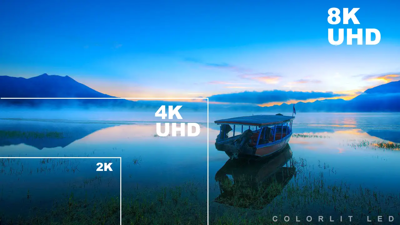
But how to choose a suitable pixel pitch?
| Model | Pixel Pitch | Resolution (Dot/㎡) |
| COB P0.625 | 0.625mm | 2560000 |
| COB P0.78 | 0.78mm | 1638400 |
| COB P0.9375 | 0.97375mm | 1137778 |
| COB P1.25 | 1.25mm | 640000 |
| COB P1.56 | 1.5625mm | 409600 |
| COB P1.875 | 1.875mm | 284444 |
As you can see from above table, flip chip COB, with its wire-free, compact design, can achieve pixel pitches as fine as 1mm or even lower, enabling true 4K and 8K resolutions in relatively small screen sizes.
A common question is: How do you select the right screen size per pixel pitch to ensure 2K, 4K, or 8K resolution?
Here we use a standard cabinet size of 600*337.5mm as an example. A 600*337.5mm cabinet is a common size to achieve a 16:9 ratio LED screen.
P1.25mm

As the above image showed, when we select P1.25, the min screen size for 2K resolution is 2400*1350mm, and the size for 4K resolution is 4800*2700mm.
We’ve listed the typical screen size associated with each resolution for your reference.
| Model | Size (W*H) | Resolution (W*H) |
| COB P1.25 | 1800*1350mm | 1440*810, 1K |
| COB P1.25 | 2400*1350mm | 1920*1080, 2K |
| COB P1.25 | 4800*2700mm | 3840*2160, 4K |
| COB P1.25 | 9600*5400mm | 7680*4320, 8K |
P1.5625mm

You can see from the above figure, for pixel pitch P1.5625, to achive 2K resolution, the screen size at least 3000*1687.5mm size. to achive 4K resolutin, the screen szie is at least 6000*3375mm size.
Below are the Min screen size for common resolutions.
| Model | Size (W*H) | Resolution (W*H) |
| COB P1.5625 | 1800*1350mm | 1152*864, 1K |
| COB P1.5625 | 3000*1687.5mm | 1920*1080, 2K |
| COB P1.5625 | 6000*3375mm | 3840*2160, 4K |
| COB P1.5625 | 12000*6750mm | 7680*4320, 8K |
P1.875mm
For pixel pitch P1.875, to achive 2K resolution, the screen size at least 3600*2025mm size. to achive 4K resolutin, the screen szie is at least 7200*4050mm size. Following is the image for your reference

For your reference, the common screen size corresponding to each resolution are listed below.
| Model | Size (W*H) | Resolution (W*H) |
| COB P1.875 | 2400*1350mm | 1280*720, 1K |
| COB P1.875 | 3600*2025mm | 1920*1080, 2K |
| COB P1.875 | 7200*5050mm | 3840*2160, 4K |
| COB P1.875 | 14400*10100mm | 7680*4320, 8K |
8. Repair and Maintenance: Is Flip Chip COB Serviceable?
One of the most debated aspects of flip chip COB is its repairability.
Unlike SMD displays, where individual LEDs can be replaced, flip chip COB modules generally cannot be repaired at the pixel level once encapsulated.
Generally solution is Module-Level Repair.
Module-Level Repair
As mentioned above, in flip chip COB, the chips are directly bonded and encapsulated as a single unit. If a pixel fails—whether due to a chip defect, electrical fault, or encapsulation issue—individual pixel repair is not practical.
Instead, the typical solution is to replace the entire module. This can be a drawback in scenarios where maintenance access is limited or repair frequency is high.
This is unlike the SMD LED screen, which can achieve Pixel-Level Repair.
Why Is Pixel-Level Repair Difficult for flip chip COB screen?
This is because the encapsulation layer that protects the chips from dust, moisture, and impact also makes it virtually impossible to access and replace individual chips without damaging the surrounding area.
While flip chip COB is not as serviceable at the pixel level as SMD LED panel, flip chip COB modules are easier to clean and less susceptible to damage from dust, liquids, or accidental impact.
For most high-end use cases, the benefits in reliability and performance outweigh the downsides.
9. Price Comparison: Flip Chip COB vs SMD vs Face-Up COB
Pricing is a significant factor in display technology selection.

Flip chip COB is generally more expensive than SMD or face-up COB, but the gap is narrowing as production scales up.
SMD LED Screen
SMD LED modules have been in mass production for years, benefiting from mature technology, large-scale manufacturing, and extensive supply chains. For pixel pitches above 1.5mm, SMD modules are the most cost-effective option, especially when factoring in ease of repair and wide availability.
Face-Up COB
Face-up COB modules are typically less expensive than flip chip COB, mainly due to lower material and process costs. However, their reliance on wire bonding and larger chip sizes limits their performance and reliability, especially as pixel pitches shrink.
Flip Chip COB
Flip chip COB modules cost more due to higher material specifications, advanced manufacturing processes, and lower initial yields. The need for specialized equipment and cleanroom conditions also adds to the cost. However, as the technology matures and scales, prices are dropping—sometimes by as much as 25% compared to early years.
Here is a summary price table for your reference:
| LED Technology | Price |
| SMD LED | The Cost Leader for Large Pixel Pitch, most effective for wide LED screen applications. Price is from $100/sqm to $2500/sqm. |
| Face-Up COB | A Middle Ground, price varies from $1000/sqm to $3000/sqm |
| Flip Chip COB | Premium Pricing for Premium Performance, very expensive ranges from $1500/sqm to 5000/sqm |
For more information about the COB LED Screen price, check this.
Cost Considerations by Application:
For large, less critical displays: SMD or face-up COB may be more cost-effective.
For fine-pitch, high-performance displays: Flip chip COB delivers greater value despite higher costs.
Price Trends
However, as demand for ultra-fine pitch, high-resolution displays increases (in control rooms, studios, retail, etc.), economies of scale are driving flip chip COB prices down.
In some markets, the price gap with SMD LED is now less than 20–25%, and this trend is expected to continue. As manufacturing scales, the price premium is shrinking, making it an increasingly attractive option for a wide range of applications.
10. Application of Flip Chip COB LED Screen
As we all know, Flip Chip COB LED Screens are mainly used for high-end screen applications where ultra-high resolutions are required.
One of the most prominent applications is in command and control centers, where high reliability and exceptional visual quality are paramount.
In addition to command centers, Flip Chip COB screens are increasingly utilized in entertainment and retail environments. Their excellent color reproduction and wide viewing angles make them perfect for immersive experiences, such as in theaters, concerts, stage, TV studios, XR, and exhibitions.
| LED technology | Application Scenarios |
| Flip Chip COB LED Screen | Corporate boardrooms, luxury retail showrooms, Command centers, general signage, retail displays, entertainment venues, broadcasting and virtual production studios, critical command, TV studio, home theater, museums, science centers, conference room, and control centers, XR, etc |
| SMD LED Screen | Stage, shopping centers, exhibition, showrooms, supermarket, broadcasting and virtual production studios, bar, hotel, critical command, airport, churches, TV studio, billboard, theater, trade show, museums, cultural centers, meeting room, and control centers, school, theater, hospital, etc |
11. The Recommendation Products
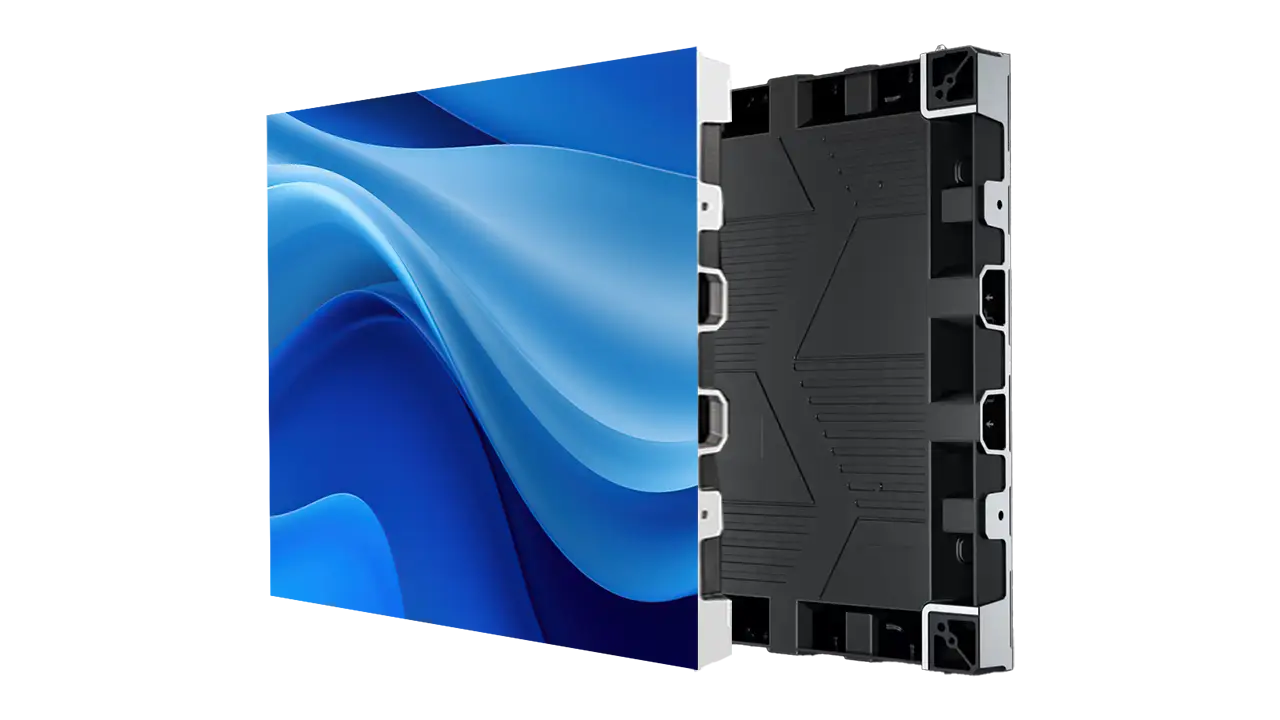
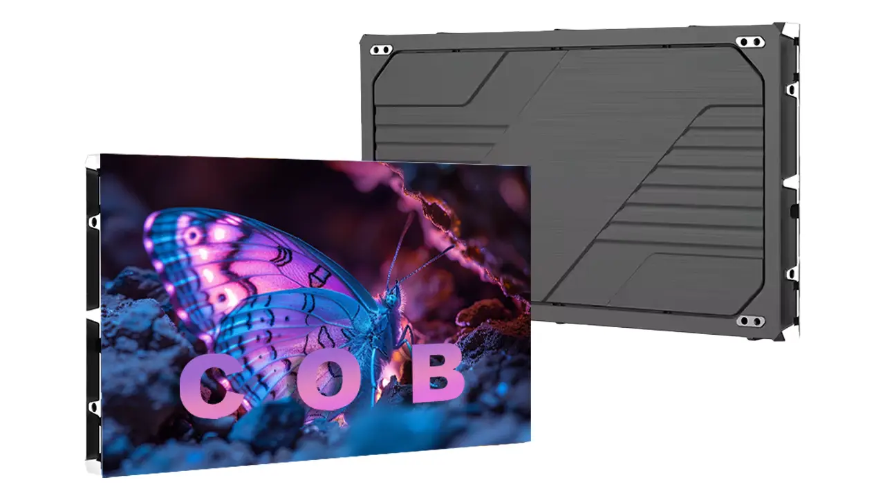
Here is our main recommendation production for flip chip COB LED panel.

12. Specification & Datasheet
Currently, the main COB LED display is using 600*337.5mm cabinets or 500*500mm cabinets to splice a large LED video wall.
The following is the common specification of a 600*337.5mm COB LED screen cabinet.
| Specification | P0.78125 | P0.9375 | P1.25 | P1.5625 | P1.875 |
| Physical density (Dot/sqm) | 1,638,400 | 1,137,778 | 640,000 | 409,600 | 284,444 |
| Module resolution | 192×216 | 320×180 | 240×135 | 192×108 | 160×90 |
| Module size (mm) | 150×168.75 | 150×168.75 | 150×168.75 | 150×168.75 | 150×168.75 |
| Panel Dimension (W×H×D/mm) | 600×337.5×27.5 | 600×337.5×27.5 | 600×337.5×27.5 | 600×337.5×27.5 | 600×337.5×27.5 |
| Panel Resolution | 768×432 | 640×360 | 480×270 | 384×216 | 320×180 |
| Module QTY (W×H) | 4×2 | 2×2 | 2×2 | 2×2 | 2×2 |
| Panel weight (kg) | 4.5 | 4.5 | 4.5 | 4.5 | 4.5 |
| Maintenance Mode | Front | Front | Front | Front | Front |
| Cabinet Material | Die-casting aluminum | Die-casting aluminum | Die-casting aluminum | Die-casting aluminum | Die-casting aluminum |
| Brightness Calibration | Yes | Yes | Yes | Yes | Yes |
| Brightness (Nits) | ≥600 | ≥600 | ≥600 | ≥600 | ≥600 |
| Color temperature (K) | 1000-18500 (Optional) | ||||
| Viewing angle (V/H) | 170°/170° | ||||
| Brightness/Color uniformity | ≥99.8% | ||||
| Contrast ratio | 10000:1 | ||||
| Frame frequency | 50/60 | ||||
| Drive mode | 1/48 scan | 1/46 scan | 1/48 scan | 1/45 scan | 1/45 scan |
| Grey level | 16bit | ||||
| Refresh rate (Hz) | 3840 | ||||
| Max. power consumption (W/sqm) | 350 | ||||
| Avg. power consumption (W/sqm) | 100 | ||||
| Protection level | IP31 | ||||
| Power input | AC90-264V, 47-63Hz | ||||
| Working temperature/humidity (℃/RH) | -20~60℃/10%~85% | ||||
| Storage temperature/humidity (℃/RH) | -20~60℃/10%~85% | ||||
| Certification | CCC/CE/RoHS/FCC/CB/TUV/IEC | ||||
The following is the common specification of a 500*500mm COB LED screen cabinet.
| Specification | P1.25 | P1.5625 | P1.875 |
| LED Type | COB 1R1G1B Flip Chip Process | ||
| Physical density (Dot/sqm) | 640,000 | 409,600 | 262,144 |
| Module resolution | 200×200 | 160×160 | 128×128 |
| Module size (mm) | 250×250 | 250×250 | 250×250 |
| Panel Dimension (W×H×D/mm) | 500×500×50 | 500×500×50 | 500×500×50 |
| Panel Resolution | 480×270 | 384×216 | 320×180 |
| Module QTY (W×H) | 2×2 | 2×2 | 2×2 |
| Panel weight (kg) | 6.4 | 6.4 | 6.4 |
| Maintenance Mode | Front | Front | Front |
| Cabinet Material | Die-casting aluminum | Die-casting aluminum | Die-casting aluminum |
| Brightness Calibration | Yes | Yes | Yes |
| Brightness (Nits) | ≥600 | ≥600 | ≥600 |
| Color temperature (K) | 1000-18500 (Optional) | ||
| Viewing angle (V/H) | 170°/170° | ||
| Brightness/Color uniformity | ≥99.8% | ||
| Contrast ratio | 10000:1 | ||
| Frame frequency | 50/60 | ||
| Drive mode | 1/50 scan | 1/40 scan | 1/64 scan |
| Grey level | 16bit | ||
| Refresh rate (Hz) | 3840 | ||
| Max. power consumption (W/sqm) | 440 | ||
| Avg. power consumption (W/sqm) | 220 | ||
| Protection level | IP31 | ||
| Power input | AC90-264V, 47-63Hz | ||
| Working temperature/humidity (℃/RH) | -20~60℃/10%~85% | ||
| Storage temperature/humidity (℃/RH) | -20~60℃/10%~85% | ||
| Certification | CCC/CE/RoHS/FCC/CB/TUV/IEC | ||
13. Conclusion
In this post, we explored the intricacies of Flip Chip COB LED displays, delving into their advantages and disadvantages. We discussed why this technology is increasingly favored in various applications, particularly in high-resolution and demanding environments.
We also talked about the price comparison with SMD LED and face-up COB. With this, you can have the right choice according to your budget.
If you found this information helpful, we encourage you to consider how Flip Chip COB could fit into your next project or installation. We hope this article has provided you with a comprehensive understanding of Flip Chip COB LED technology and its potential to revolutionize display solutions. If you are looking for a high-quality Flip Chip COB LED screen, you can contact us at any time.


